

![]()
Bending Dies:
For all Tooling: Part Number proceeding with 114, 138, 112, Etc. Shows the
diameter of tube to use with that tool.
Example: 35R-114 (3.5” Radius Die that will bend 1 ¼“ tube)
Suffix
|
Diameter |
|
Suffix |
Diameter |
|
114 |
1 ¼” |
|
138 |
1 ⅜” |
|
112 |
1 ½” |
|
158 |
1 ⅝” |
|
134 |
1 ¾” |
|
178 |
1 ⅞” |
|
200 |
2” |
|
214 |
2 ¼” |
|
300 |
3” |
|
212 |
2 ½” |
Prefix
|
Radius Die |
|
35R |
3 ½” |
|
4R |
4 |
|
5R |
5 |
Number
|
Radius Dies 180° |
4R*** / 180
|
4” |
|
5R*** / 180 |
5” |
|
BP / 180 |
Blank Plate, To be used in conjunction with the 4R/5R 180° Dies |
Shoes (1 Pair):
Prefix
|
Description
|
QS
|
Quarter Shoe |
|
HS |
Half Shoe |
|
TS |
Three Quarter Shoe |
|
BS |
Back Shoe |
Prefix
|
Description |
BM
|
Male Ball |
|
ED |
Expander Die |
|
ED / RT |
Expander / Reducer Tool |
|
RT |
Reducer Tool |
Hinged Adapter Collars:
|
Prefix |
Description |
|
AC |
Adapter Collar |
Expander Tooling:
|
Prefix |
Description |
|
SS |
Segment Set |
|
BSS |
Ball Segment Set |
Ball Segment Sets:
|
Prefix |
Description |
|
BSS |
Ball Segment Set |
Arbors:
|
Prefix |
Description |
|
HSA–1 |
Arbor for 1 ½” to 3” |
|
HSA-2 |
Arbor for 1 ¼” to 1 3/8” |
Reducer and Flange Tools:
|
Prefix |
Description |
|
RT |
Reducer Tool |
|
CFT |
Chevy Flange Tool |
|
Prefix |
Description |
|
HPF |
Flair / Flange Tool 45° / 90° |
|
DD |
Doming Die |
|
BF |
Female Ball Tool |
|
HCT |
Head Collector Tool |
|
QAD |
Quick Adapter Disconnect |
|
HSA |
Round Arbor |
|
HST |
Hand Sizing Tool |
|
B-1 |
Reducer Bushing (Arbor) |
|
LN-1 |
Lock nut (Arbor) |
Pipe Plugs:
|
Prefix |
Description |
|
PP |
Pipe Plug |
Accessories:
|
Prefix |
Description |
|
RD |
Rotational Dial |
|
CD-* |
Program Card Deck |
|
ACC-100 |
“O” Ring Assortment Kit |
|
ACC-300 |
Rotational Bend Angle Dial |
|
SM-100 |
Service Manual |
|
Item |
Description |
|
Front |
Where all bending is performed. |
|
Rear |
Where all Tube-End forming is done. |
|
Left |
As you face the bender from the front. |
|
Right |
As you face the bender from the front. |
Expanders:
|
Item |
Description |
|
Swage |
For all sizing operations using push die tooling. |
|
Arbor |
For all sizing operations using an arbor and segment sets. |
|
Pusher Block |
The solid steel block fixed to the shaft of the bending cylinder on top
of the machine. |
|
Swage / Expander |
A double ended cylinder, which combines the features of both the swage
and arbor expander in a single unit. |
Use the space below for
notes and special details:
![]()
About Your EZEBEND™ Tube Bender
The
EZEBEND™
Tube Bender is a product of years of continuous research, development,
and product improvement. Following the simple installation and maintenance
instructions given herein will insure you long efficient and trouble free
service.
EZEBEND™ tube benders are manufactured with the
finest materials and components available. They are equipped with rugged
precision tooling, designed for day to day production in your shop.
Throughout this manual we will cover detail differences from model to model. The
basic frame design is the same on most models. This manual covers the
installation, maintenance, and use of various models. Skip over parts of the
manual that tell about features your machine does not have.
EZEBEND™ tube benders perform two functions:
(1)
They bend tubing of diameters within their tooling capacity to specified angles
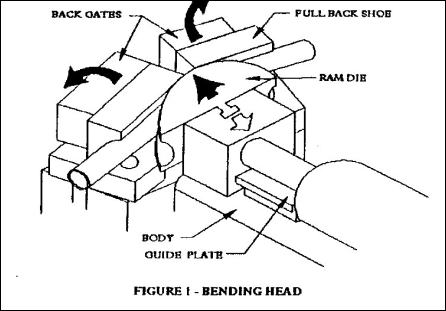
and radii (See Figure 1).
(2)
They expand or form the ends of tubes to specified configurations
(See Figure
2).
Tube bending is done with hydraulically driven ram die and a matching pair of
back shoes. Tubing is held in place prior to bending by spring pressure on
the ram die. When the operator is sure the tubing is positioned properly, he
activates the machine (Figure 1).
The ram die moves smoothly forward. The back shoes swing smoothly back,
continually exerting pressure against the ram die, while allowing it to pass
between the matching ram die and back shoes. Hold the tubing securely while
bending it through the correct angle. After the desired depth of bend is
achieved, the ram die retracts, (manually or automatically, depending on the
machine model), releasing the bent tubing.
The expanding and shaping capability is performed in two distinct ways. These are called, respectively, swaging and expanding. Both swaging and expanding capabilities are found on some models of EZEBEND™ tube benders.
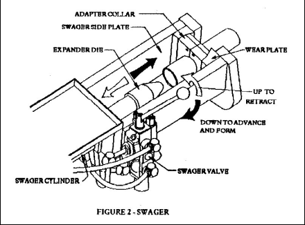
In the swaging operation (Figure 2), the tubing and adapter collars are inserted in the clamp assembly. An expander die is pushed hydraulically into the open end of the tube. As pressure is applied to the tube end, the hinged adapter collars slide together to restrain the tube securely.
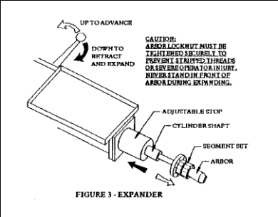
In the expanding
operations (Figure 3), the tube is placed over the segment set and arbor. As the
tapered arbor is hydraulically withdrawn, the segment set comes into contact
with the adjustable stop, which causes the segment set to expand outward, thus
expanding the tube end.
Always use your
EZEBEND™ tube bender on a solid, level floor,
sturdy enough to support the weight of the machine properly.
While all actions of the
EZEBEND™ Tube Bender are hydraulic, primary power
is electric. The machine makes use of a hydraulic pump, driven by an electric
motor. The pump is always located beneath the main body, coupled to the motor
shaft.
Two kinds of electric motors are available, on customer specification,
single-phase and three-phase.
![]()
Electrical Hook-up (Single Phase):
All single-phase
EZEBEND™ Tube Bender is factory pre-wired with a
plug. No receptacle is shipped with the machine. The standard receptacle for
this plug is found in many commercial and industrial buildings. It is also
readily obtained at hardware or electrical supply stores.
The receptacle should be wired into a junction box which supplies a full 220
volts, single phase, 60 cycles, properly fused or breaker protected. A qualified
electrician best does this receptacle hook up.
Checking Rotation Direction (Single Phase):
Rotation is preset at the factory for all single-phase motors. No rewiring
should be necessary. However, if for any reason motor wiring is adjusted,
immediately check the motor shaft to insure counter clockwise rotation as view
facing the motor shaft.
Caution:
If the shaft turns in the wrong direction shut the machine off immediately!
Prolonged running in the clockwise direction will damage the pump shaft seals.
Unplug the machine and correct the internal motor wiring by referring to the
motor schematic.
Electrical Hook-up (Optional: Specially Requested / Three Phase Motor)
Three phase benders are factory pre-wired with a standard four-prong plug.
Receptacle instructions are the same as the single phase. Please review those
instructions above.
Checking Rotation on Three Phase is the same as Single Phase. See ‘Checking
Rotation Direction (Single Phase):’
Operating Your Machine for the First Time
All
EZEBEND™ Tube Benders make use of the rear
pedestal of the machine as the hydraulic fluid reservoir. This reservoir is
filled to the proper level at the factory.
With the motor off, check the Site gauge on the rear pedestal to make sure the
reservoir is filled with fluid to the proper level. At any time the level of the
fluid visible in the Site gauge is less than half the way to the top of the
gauge, refill the reservoir with one of the approved hydraulic fluids listed in
the appendix of this manual. Never start or operate the machine unless the
hydraulic reservoir is filled to the proper level.
The various models of
EZEBEND™ Tube Benders are similar in design and
configuration. But the hydraulics and controls vary from model to model. It is
important that you become familiar with the particular model you are using,
prior to checking out the hydraulic circuits and operation of the machine.
Models vary first in swaging and expanding equipment. They also vary in mode of
operation. All
EZEBEND™ Tube Benders, (except the model 250),
have bending capacity ranging from ½” through 3” tube diameter and up to 180°.
All standard models have a 5 hp, 220-volt single-phase motor. Different voltages
and phases are available for most models as an option. Please call for a quote
before ordering a bender with an optional package.
Model
Description
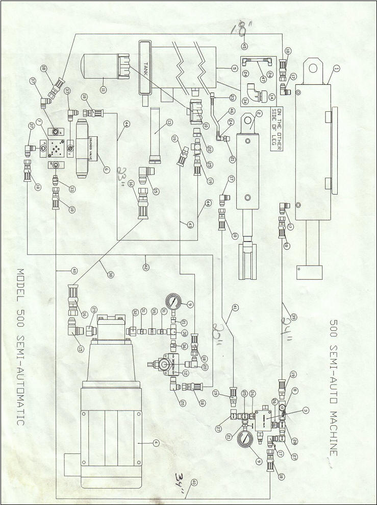
500
Full-size, standard bend only tube bender without end forming capacity.
Semi-automatic (SA) option available with remote electric foot pedals,
available in standard 5 hp version or High Speed / Extra Capacity with a
7.5 hp motor.
1000
Full-size, standard manual tube bender with knee control operation and a
double ended Expander / Swage.
2000
Manual tube bender with manual foot pedal control operation and double
ended Expander / Swage.
3000
Manual tube bender with knee control operation and independently
operated Expander and Swage.
5000
Semi-Automatic control with remote electric foot pedals and double ended
Expander / Swage.
6000
Semi-Automatic controls with remote electric foot pedals and
independently operated Expander and Swage
Machine Familiarization and Operation:
After you have completed electrical setup and acquainted yourself with its
particular model features, you are ready to check out the machine operation.
Your
EZEBEND™
Tube Bender has been thoroughly factory
tested, all adjustments have been made for proper operation. However, it is good
practice to familiarize yourself with hydraulic system pressures and machine
operation. While you do this, you will assure yourself that your machine is
setup correctly.
Power-Beyond (5 Port or 7 Port) Valve:
Your
EZEBEND™ Tube Bender with Expanding capability has
a power beyond valve mounted near the rear of the machine. All hydraulic fluid
output of the pump is directed to this valve, which regulates pressure for the
entire hydraulic system.
Five and Seven Port Valves:
The valve has five or seven ports, depending on the model, and each port has a
hydraulic connection. However, design and appearance of the valve will vary
somewhat among various machines and models due to different component suppliers.
The power beyond valve always has a pressure gauge associated with it. This
gauge is mounted on the output or pressure side of the pump. Since the power
beyond valve regulates pressure for the whole machine, its output is applied
directly to the top cylinder. This is the basic pressure beyond the valve; thus
the name “Power Beyond” valve.
Full pressure will register on the gauge only with the expander cylinder fully
extended or retracted. Do not leave and cylinder fully extended or retracted
with the valve open for any length of time.
Checking the Power Beyond Valve Adjustment:
To check the operation of the power beyond valve, proceed as follows (Figure 4).
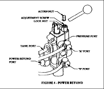
Actuate the expander control valve. The ram should extend fully and smoothly
until the cylinder bottoms out. Read the pressure gauge near the pump. The gauge
should read 2800-3000 PSI.
If the gauge does not register correctly within plus or minus 50 PSI, adjust the
pressure following these steps:
|
Step |
Description |
|
A |
On, or adjacent to, the Power Beyond valve there is a large acorn nut.
This serves as a cover for the pressure adjusting screw. Remove the
acorn nut. |
|
B |
Loosen the lock nut. Turn the threaded relief valve shaft clockwise to
increase pressure, or counter clockwise to decrease the pressure. |
|
C |
Tighten the lock nut, holding the threaded screw in position. |
|
D |
Check the adjustment with another retraction and bottoming of the
expander cylinder. Readjust, if necessary, beginning at step “B”, to get
the correct reading. |
|
E |
Replace the acorn nut when you have made the correct adjustment. |
Sequence Valve Adjustment (Figure 5A)
The sequence valve regulates the amount of pressure in the bottom cylinder. This
cylinder holds pressure on the back shoes through a single leaf chain attached
to the bottom of each gate.
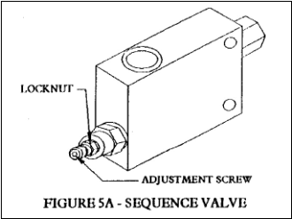
The sequence valve is located on the front pedestal of the machine at knee
level. The sequence valve pressure gauge is mounted on the valve itself and is
supplied with a pressure adjustment screw, like that of the Power Beyond valve.
To check sequence valve pressure, take the following steps:
Step |
Description | |||
1 |
Read the sequence valve gauge while running the ram die out to the depth
of bend between 40° to 60°. | |||
2 |
The sequence valve pressure should be between 1400 and 1800 PSI, in
order to bend tubing of 2 ½” or less diameter. | |||
3 |
If adjustment is required, loosen the lock nut and turn the adjustment
screw clockwise to increase pressure, or counter clockwise to decrease
pressure. |
|
CAUTION |
|
Do not exceed 1800 PSI on a day to day basis. Excessive sequence valve
pressure will cause premature wear to bending dies and back shoes. |
High initial back gate pressure is required when bending 3” tubing in order to
get good, uniform bends. Good bends will normally result only when 13 gauge
(.095” wall thickness) tubing is used. Good quality 14 gauge AK or H.R.E.W.
tubing may also be used. Lesser quality or narrower gauge material may result in
tube damage and / or bending inconsistency.
When having trouble bending 3” diameter tubing, use the following special
procedure. Note: Use either the manually operated front control valve or the
forward and reverse foot pedals. Do not use automatic push buttons.
Step |
Description |
1 |
Install 3” bending dies. Set the sequence valve pressure between 1600
and 1800-PSI by turning the adjustment screw clockwise to increase
pressure.
Caution: Do not attempt to turn beyond the jam nut position. Further
adjustment may cause valve stem leakage. |
2 |
Position the tubing in the bender and begin the bend. Be sure to use
only the front control valve or the foot pedals. |
3 |
At a depth of bend between 30° and 40°, start to reduce sequence valve
pressure by turning the adjustment screw counter clockwise until you
have a gauge reading of about 400 PSI. |
4 |
If the bender bogs down, further reduce the sequence valve pressure on
the back gates and continue bending and reducing the pressure until the
desired depth of bend is reached. |
5 |
If further 3” diameter bends are required, repeat the procedure, staring
with step one. Otherwise reset the sequence valve pressure between 1400
and 1600-PSI. |
![]()
Flow Control Valve Adjustment (Figure 5B)
The flow control valve regulates gate return or back pressure on the bottom
cylinder by creating a slight pressure differential between the top and bottom
cylinders. This is the pressure that closes the back shoe gates after a bend.
This valve is the hexagon shaped valve located near the sequence valve.
Step |
Instruction |
1 |
Run the ram out until the ram die engages the back shoes and the gates
open to between 40° and 50°. |
2 |
Retract the ram. |
3 |
At the instant the back gates close (About the moment when the ram die
disengages from the back shoes), the pressure should register 300 to 400
PSI on the sequence valve gauge. |
4 |
If the pressure is not within these limits, loosen the allen set screw
on the knob. |
5 |
Turn the knob clockwise to increase pressure, or counter clockwise to
decrease the pressure. |
6 |
If one or more of the back gates hesitate or remain open after
disengaging, increase the flow control pressure. |
7 |
If the ram hesitates when returning, wait until the die is not touching
the back shoes, and then adjust the flow control pressure while cylinder
is still engaged. If the back shoes dig into the tube when returning.
Decrease the flow control pressure. |
8 |
After the proper setting is obtained, tighten the setscrew. |
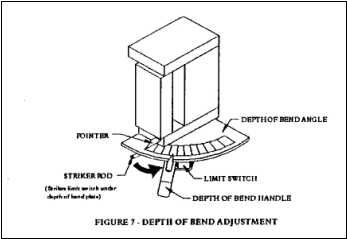
Setting the Bend Angle: (Figure 6)
To check the depth of bend for adjustment, use a carpenter’s square or
equivalent 90° square. Proceed as follows:
Step |
Instruction |
1 |
Run the gates out manually, holding the square against the back of the
gates. |
2 |
Jog the gates back and forth until the square rests flush against the
back of each gate. The back gates are now set physically at 90°. |
![]()
Semi-Automatic Models 5000-6000 | |
Step |
Instruction |
1 |
Check to insure the pointer is tightly bolted to the right back
gate. |
2 |
With the back gates set at 90°, using a carpenter’s square, tap
the pointer lightly, if necessary, to read exactly 90° on the depth of
bend plate. Also check to be sure the depth of bend pointer returns to
0°. |
3 |
After the pointer has been adjusted, with back shoes and ram die
in machine, move depth of bend handle to 90°. Push the forward foot
pedal while watching the gate pointer, the gate pointer should line up
with the pointer of the depth of bend handle when the gate stops. |
4 |
If the pointers do not line up, adjust the depth of bend plate
limit switch as follows:
Loosen allen set screw on striker rod. If the gate pointer goes
past the depth of bend pointer handle, pull the striker rod slightly
away from the frame of the machine and tighten the set screw. If the
gate pointer does not reach the depth of bend handle pointer, push the
striker rod slightly toward the frame of the machine and tighten set
screw. |
5 |
Repeat steps three and four until the two pointers line up. |
Step |
Instruction |
1 |
Check to insure the pointer is tightly bolted to the right back
gate. |
2 |
With the back gates set at 90°, using a carpenter’s square, tap
the pointer lightly, if necessary, to read exactly 90° on the depth of
bend plate. Also check to be sure the depth of bend pointer returns to
0°. |
![]()
Properly used, your EZEBEND™ Tube Bender will give you continuous and reliable service. There are minor problems, which may occur from time to time, which you can readily correct, as well as good operating practices, which help you avoid problems.
Familiarity with the use and operation of your bender includes knowledge of good
operating practices, and trouble shooting minor problems.
Always have a full set of dies in place whenever you operate the top cylinder. Operating without dies will cause severe damage to your bender.
Never extend the bending die beyond the back shoes. Such action can cause severe damage and may result in having to disassemble the gates in order to remove tubing. Avoid bending beyond the following depths with the bend radii given when possible.
|
Die |
Maximum recommended bend |
|
3 ½” |
130° |
|
4” |
150° |
|
5” |
160° |
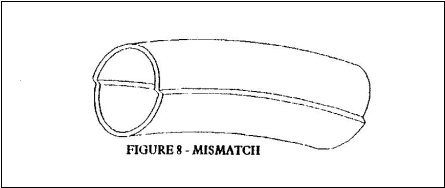
If Bends Indicate Mismatch: (Figure 8)
|
Step |
Instruction |
|
1 |
First check to see that back gate top plates are clear of debris which may be causing back shoes to rest slightly higher than the ram die. |
|
2 |
Using a straight edge, check to be sure that guide plate and back gate top plates are at approximately the same level. (Guide Plate: +.000” to -.010”) |
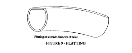
If the Outside Diameter is Flattened after Bending:
|
Step |
Instruction |
|
1 |
The sequence valve bend pressure is too low. Adjust as described in ‘Sequence Valve Adjustment (Figure 5A)’. Note: High sequence valve pressures can cause bottom cylinder rod damage, or master link damage. Do not exceed recommended pressures. |
If the Tubing is Crimped on the Bend Inside Diameter: (Figure 10)
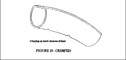
Check back gate alignment as described in, ‘Setting the Bend Angle: (Figure 6)’. Increase sequence valve pressures as described in ‘Sequence Valve Adjustment (Figure 5A)’. If this does not solve the problem check the thickness of the tubing you are using. Minimum thicknesses for consistently good bends are as follows:
|
Gauge |
Diameter |
|
16 (.065) |
Up to 2 ¼” |
|
14 (.083) |
2 ¼” to 2 ½” |
|
13 (.095) |
3” |
If the Tubing is Sucked in on the Bend Outside Diameter: (Figure 11)
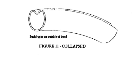
While this is almost always an indication that tubing wall is too thin, also check sequence and flow control pressures, as described in ‘Sequence Valve Adjustment (Figure 5A)’ and ‘Flow Control Valve Adjustment (Figure 5B)’.
If the Back Gates do not Close Evenly:
Check flow control valve pressure, as described in ‘Flow Control Valve Adjustment (Figure 5B)’.
If the Back Gates Hesitate When Closing or Back Shoes Dig into the Tube When Closing:
Adjust the flow control valve, as described in ‘Flow Control Valve Adjustment (Figure 5B)’.
Caution: Swaging pressure is factory set. Do not attempt to change factory pressure setting.
Always check to make sure the quick release adapter is tightened securely to swage cylinder shaft. A loose adapter can cause threads to strip due to the extreme pushing force of the swage cylinder. Also be sure to keep adapter groove or slot clean of debris that may prevent the expander die mating portion to drop fully into the centerline position.
Caution: Avoid expanding into hinged adapter collars. Avoid hitting the adapter collar, as this leads to premature wear of collars and clamp assembly.
To calibrate your EZEBEND™ Tube Bender segment sets follow this recommended procedure:
|
Step |
Instruction |
|
1 |
Install 2” slip segments (Two groves in base.) |
|
2 |
Set sizing collar on line 1 for 2” slip connection. |
|
3 |
Retract cylinder to expand tube. Be sure to round out expansion by
rotating the tube slightly and retracting arbor two or three times. |
|
4 |
Check expansion by inserting another tube of 2” diameter in the end of
previously expanded test pipe. If the expansion is too great, loosen
lock nut on arbor and unscrew arbor counter clockwise one revolution.
Secure lock nut and repeat this step from the beginning. If the
expansion is too tight, reverse this procedure.
Note: Always be sure the arbor lock nut and bushing are tight. Loose
tools can cause severe operator injury. Never stand in front of arbor
while calibrating or during normal operation!
Caution: Whenever inspecting or repairing the electrical system, unplug
your bender. |
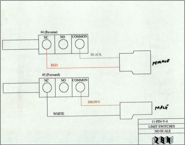
Solenoid Valve: (Figure 12)
The solenoid valve controls the direction of the bending operation of semi-automatic EZEBEND™ Tube Benders. It is attached close to the rear pedestal leg on the left side.

Noisy Motor / Pump Combination:
A whining or growling from the motor / pump can be indicative of a damaged pump. Continued operation can cause serious damage to all components in the hydraulic system. Always locate the source of the unusual noise and correct them immediately for extended service life.
|
Step |
Instruction |
|
1 |
Check for counter clockwise
shaft rotation as described in ‘Checking Rotation Direction (Single
Phase)’. |
|
2 |
Check the fluid level with motor off. Low fluid level will cause pump cavitations. |
|
3 |
Check to insure that the motor and pump are securely fastened to the mounting plate. If either one of the above is loose, tighten as necessary. |
|
Step |
Instruction |
|
Check that the flow control valve on the left side of the bender has not closed. You should see colored bands. Flow Control Valve | |
|
2 |
If closed (no or few color bands are exposed), turn the knob to open and check that all the colored bands are visible. Retighten the set screws on the knob to keep the valve from closing. |
|
3 |
Check that there is system pressure. If there is no pressure, yet the motor is running, check the couplings that attach the hydraulic pump to the motor. With the power off and the unit unplugged, open the access panel underneath the housing between the pump and the motor (usually orange in color). |
|
4 |
Check that a rubber spider is between the coupling teeth. The couplings should have the spider between either side with almost no gap between each piece. Try to move the couplings by hand by rotating on the shaft or forward/backward motion along the shaft,. They should not move. If they slip easily, retighten the set screws on both couplings. Confirm that the key is secure in the keyway and is not broken or missing. If missing, look in housing; replace if broken or missing. |
|
Step |
Instruction |
|
1 |
Grease the zerk fittings on the left barrel and the right barrel. |
|
2 |
Grease the zerk fittings on each wheel caster (Using SAE 90 in each instance). |
|
3 |
Check the Site gauge and refill the reservoir as required. |
|
4 |
Check motor, pump valve and cylinder mounting bolts for tightness. |
Replace fluid and filter on hydraulic system.
Do not use transmission fluid!
Transmission fluid often has additives, which are harmful to valve, and the cylinder seals and often results in leaks. Use one of the following approved oils in your machine(s).
|
Mobile DTE 24 |
ARCO Eagle RSO-X Light |
|
Texaco Regal BR & O |
Chevron OC Turbine 11 |
|
Shell Turbo 29 |
Union RL Turbine 225 |
If there is a visual change in the color of your hydraulic oil, particularly if the oil develops a grayish appearance (this indicates water in the hydraulic system), completely drain the hydraulic system and reservoir, clean the tank strainer and change the filter prior to refilling the machine with fresh hydraulic oil.
Do not dampen / wet electrical components or wiring!
Do not grease motor!
With proper care your EZEBEND™ Tube Bender should give you a lifetime of quality, trouble free service.
Pattern Bending:
|
Step |
Instruction |
|
1 |
Determine the proper tube diameter based on the vehicle you are working on and then select a matching set of bending dies. Check the bend radii in the sample by physically inserting a ram or bumper die into the bends in the sample. Record the die sizes you will use, the tube diameter and all other essential details on a piece of paper or notebook. (Or a blank BRADSHAW card, remember Blue for cars and gray for trucks.) |
|
2 |
Install the dies on your bender and insert the tubing you will bend between the dies so that the left end of the tube is flush with the end of the left back shoe and the rest of the tube extends out of the right side of the bender. |
|
3 |
Advance the bending cylinder so that the tube is snugly held between the bending die and the two back shoes. The seam of the tubing should always face up for your first bend. |
|
4 |
Insert your rotation dial into the right end of the tube and set at “0” directly over the seam of the tube. Zero rotation is always shown in the first bend column on your BRADSHAW card. |
|
5 |
Place the sample you are going to copy over the back shoes and adjust the tube in the bender to the left so that it matches the length of the sample up to the first bend in it. Record the distance from the left end of the tube to the center of the back shoes. (Theoretically to enter of your fist bend). Place the symbol ‘F’ in the first column to designate the starting point. |
|
6 |
Using only the electric foot pedals (automatic models) or the manual pedal control (manual models) proceed to bend until you have matched the bend in the sample. Record the bend depth on your care (by reading the digital read out on automatic models or the Depth of Bend plate on all non-automatic models). Also note the bend number: i.e. 1, 2, 3, 4, etc. |
|
7 |
Advance the tube in the bender sufficiently to match up with the second bend in the sample. Place the sample over the back shoes and align the first bend in both pieces. Adjust the tube in the bender so that you have sufficient distance to line up with second bend in sample as it is centered over the back shoes. Now measure the distance from the center of your first bend to the center of the back shoes and record this center mark on your care, paper, etc., along with the rotation reading once tubes are aligned. |
|
8 |
Proceed as above and record every step until complete. |
![]()
EZEBEND™
TUBE-BENDING MACHINES ARE OF SUCH QUALITY IN MATERIALS AND PROFESSIONAL
WORKMANSHIP BRADSHAW MFG., INC. IS ABLE TO OFFER ITS' CUSTOMERS A LIFETIME
LIMITED WARRANTY. THE FEATURES OF THE WARRANTY ARE AS FOLLOWS
1.
BRADSHAW WARRANTS THE COMPLETE WELDED FRAME AND COMPONENTS OF
EZEBEND™ Tube Benders TO BE FREE FROM DEFECTS IN
MATERIAL AND WORKMANSHIP FOR TWO YEARS (2) FROM PURCHASE DATE, UNDER NORMAL USE
AS DELIVERED TO THE ORIGINAL PURCHASER.
2.
BRADSHAW WARRANTS THE HYDRAULIC CYLINDERS, ELECTRIC MOTOR AND ALL
BENDING DIES, (RADIUS DIES, BACK SHOES, HALF SHOES AND THREE-QUARTER SHOES) FOR
ONE (1) YEAR FROM DATE OF INVOICE, UNDER NORMAL USE AS DELIVERED TO THE ORIGINAL
PURCHASER.
3.
BRADSHAW WARRANTS THE END FINISHING TOOLING, SOLID AND SEGMENTED,
ELECTRICAL, AND HYDRAULIC COMPONENTS FOR ONE YEAR FROM DATE OF INVOICE, UNDER
NORMAL USE AS DELIVERED TO THE ORIGINAL PURCHASER.
THIS WARRANTY DOES NOT APPLY TO NORMAL WEAR OR TO MISUSE. BRADSHAW IS
THE SOLE JUDGE IN WARRANTY JUDGMENTS.
DEFECTIVE PARTS COVERED BY THIS WARRANTY WILL BE REPLACED OR REPAIRED,
AT THE OPTION OF BRADSHAW, RETURNED PREPAID TO THE HOME OFFICE, WITHIN THE
APPLICABLE WARRANTY PERIOD. NINETY DAYS FROM DATE OF ORIGINAL INVOICE,
REPLACEMENT PARTS WILL BE SHIPPED TO THE PURCHASER FREIGHT COLLECT.
OTHER THAN THE WARRANTY WITH REFERENCE TO THE REPAIR OR REPLACEMENT OF
DEFECTIVE PARTS AS MORE SPECIFICALLY SET OUT HEREIN. BRADSHAW MAKES NO
WARRANTIES, EXPRESS OR IMPLIED, OF MERCHANTABILITY OR OTHERWISE, WHICH EXTEND
BEYOND THE DESCRIPTION OF THE PRODUCT. IN NO EVENT WILL THE SALES
REPRESENTATIVE, WHOLESALE DEALER, BRADSHAW, OR ANY COMPANY AFFILIATED WITH IT OR
THEM BE LIABLE FOR INCIDENTAL OR CONSEQUENTIAL DAMAGES OR INJURIES, INCLUDING
BUT NOT LIMITED TO LOSS OF PROFIT, RENTAL OF SUBSTITUTE EQUIPMENT OR OTHER
COMMERCIAL LOSS, PURCHASER’S SOLE AND EXCLUSIVE REMEDY BEING AS PROVIDED HEREIN.
THIS WARRANTY MAY NOT BE ENLARGED OR MODIFIED IN ANY MANNER WHATEVER
EXCEPT IN WRITING SIGNED BY AN EXECUTIVE OFFICER OF BRADSHAW.
IT IS THE POLICY OF BRADSHAW TO IMPROVE ITS PRODUCTS WHENEVER IT IS
POSSIBLE AND PRACTICAL TO DO SO. BRADSHAW RESERVES THE RIGHT TO MAKE CHANGES OR
ADD IMPROVEMENTS AT ANY TIME WITHOUT INCURRING ANY OBLIGATION TO MAKE SUCH
CHANGES OR ADD SUCH IMPROVEMENTS TO PRODUCTS PREVIOUSLY SOLD.
ALL MOTORS, VALVES, ELECTRIC COMPONENTS, PUMPS, ETC ARE WARRANTED BY THE
MANUFACTURE. BY CONTACTING THE HOME OFFICE, EZEBEND™ WILL CONVEY INFORMATION
CONCERNING THE CLOSEST WARRANTY DEPOT FOR THE MOTOR. ALL FREIGHT, REMOVAL, AND
INSTALLATION IS THE RESPONSIBILITY OF THE END-USER.


Bradshaw Mfg,. Inc. 9627 Clinton Rd, Brooklyn, OH 44144-1029 Phone:
(800) 873-0891 · (216) 281-8585 Fax: (216)
281-8586
E-mail:
info@ezebend.com
Web Site:
www.ezebend.com We
accept Visa and MasterCard
Visit our other
product line of PVC Bending Equipment and Accessories. Web Site:
www.ezbend.com
Email:
pvcbend@ezbend.com